
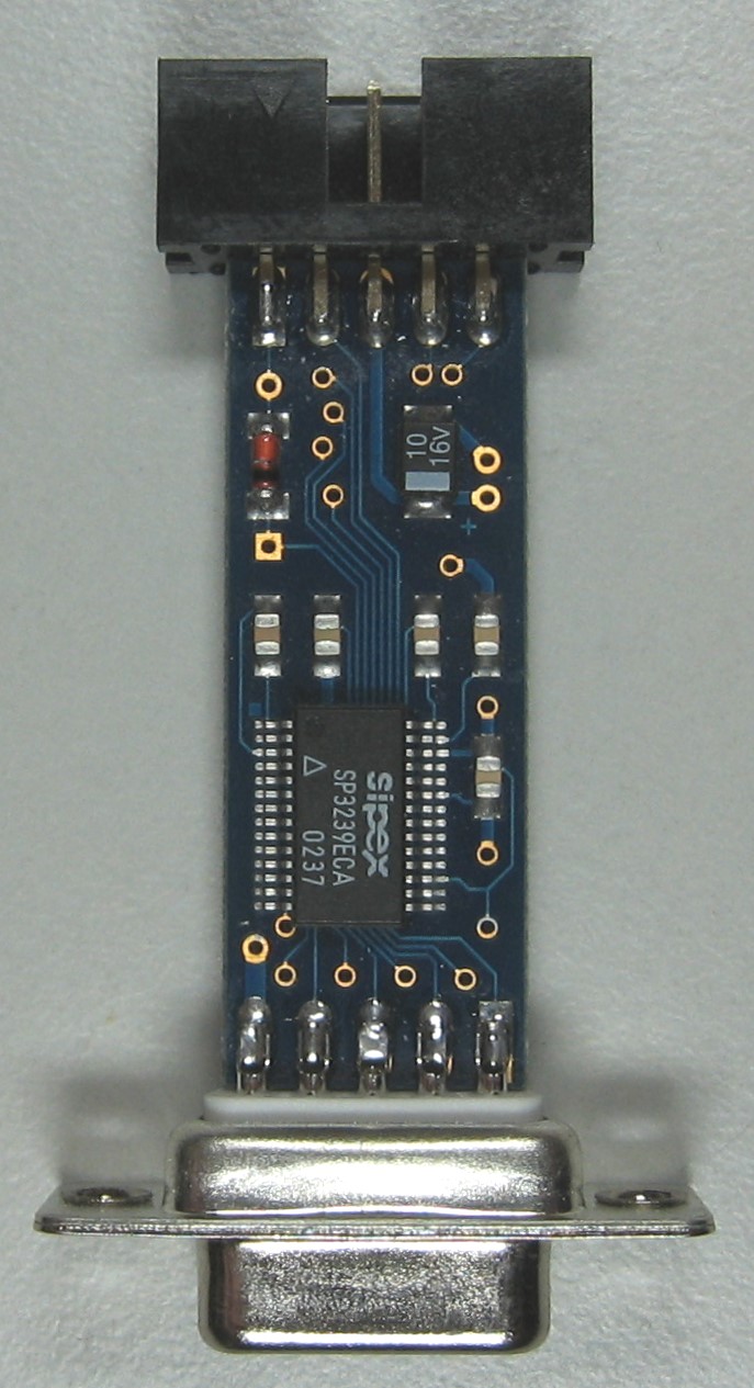
 In 2002 we defined a proprietary 10pin header for all our microcontroller-designs to connect a serial debug terminal to the µC. Therefore we designed a LVTTL-RS232 interface which fits into a DB9-donglebox with standard RS232 signals on a DB9-female connector. To meet the requirements of our various designs, the interface handles signal-levels from 2,7V up to 5,5V inside and converts them to standard RS-232 levels. Six pins were defined with serial functions Tx, Rx, RTS, CTS, Ground and Vcc. To make developement cycles more easy, we connected additional four pins to System-Reset and two pins have been reserved for acces to i2c-Bus on some systems. System Reset is open drain and could be asserted by the serial DTR line.
On EScape we added the Debug connector to make BeagleBone’s debug console (uart0) available. System-Reset can be activated by DTR and as an option it is possible to activate BBB’s Power-Button with the CTS-line. Therefore an optional rectitfier must be mounted on position D37.
We did not connect the BBB’s i2c-port, because there is a extra connector for that on the ES-board. The remaining three pins have been connected to the GPIOs that werde used for LCD-cape pushbuttons (UP,LEFT,RIGHT). Maybe we will use it for an external datawheel with pushbutton later …
Used Pins on EScape’s Debug connector are:
1 : SYS_RESET
2 : GPIO3-19
3 : GPIO1-16
4 : GPIO1-17
5 : SYS_3V3
6 : TxD (from Uart0)
7 : GPIO1-28
8 : RxD (to Uart0)
9 : PWR_BUT (if D37 mounted)
Technical details for debug adapter can be found here …
Neueste Kommentare